WINDHILL's High Voltage Test Solution for Electric Vehicle Enabling Electric Vehicle Performance Evaluation and Optimization
With the requirements of electric vehicle road testing, WINDHILL and IPETRONIK, Germany, jointly launched a high-voltage test solution for electric vehicles. Two types of measurements are commonly used for EV testing: the first is the measurement of analog signals, including voltage, current, temperature and high voltage; The second is to use a datalogger or CAN card to read data from the vehicle bus. Voltage measurements are used to determine output stability and how well the battery is working; Current measurements are used to analyze the generation, consumption, flow and recovery of energy; Temperature measurements are used to determine the operating condition of the battery and the operation/heat dissipation of the high voltage components. ECU information read by a CAN card or data logger helps us to capture residual power SOC, HV loop interlock status and insulation resistance.

I. Voltage Measurement
The system components for voltage measurement are shown below. The left end of the illustration is the measurement point, which will pass through the high-voltage current limit in the human body safety current below 2mA, and then pass through the high-voltage isolator which will be 0~1500V high voltage converted to 0~2V safety voltage, this part of the equipment works to ensure the personal safety of the test engineers. After that, the voltage signal will pass through the isolation module, and pass through the analog module which will be converted into a high-speed CAN signal, then it can be transmitted to the host computer software through the datalogger or CAN card, in order to capture the data display and analysis.
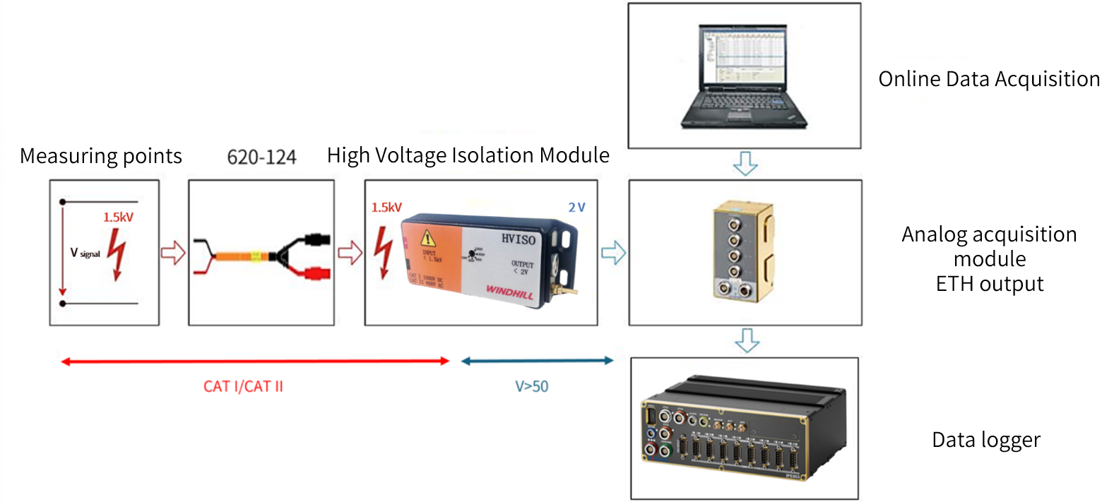
(Voltage measurement system)
II. Current Measurement
The system components for current measurement are shown below. The left end of the illustration is the measurement point, which will pass through the current sensor such as current clamp to capture the current on the cable, and then through the current isolator which will be converted from high-voltage signals to low-voltage signals, this part of the equipment works the same as voltage testing to ensure the personal safety of the test engineer. After that, the voltage signal will pass through the isolation module, and pass through the analog module which will be converted into a high-speed CAN signal, then it can be transmitted to the host computer software through the datalogger or CAN card, in order to capture the data display and analysis.
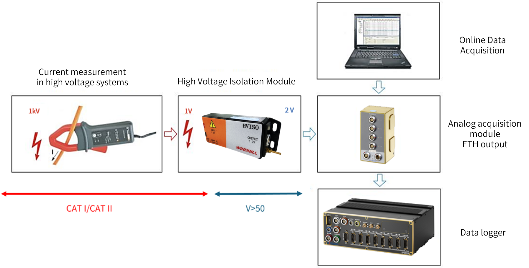
(Current measurement system)
The current clamp in the system can also be replaced with a high voltage shunt for current measurement in the power distribution box section. In addition, the two connectors can be customized to meet actual requirements.
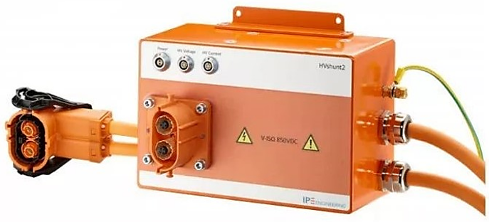
(High-Voltage shunt)
III. Temperature Measurement
The composition of the temperature measurement system for the high voltage section is shown below. For example, to measure the temperature of the battery surface: at the far left is the high-voltage temperature thermocouple, which is plugged into the high-voltage temperature measurement module, and the data will be transferred to a datalogger or to a PC via a CAN card.
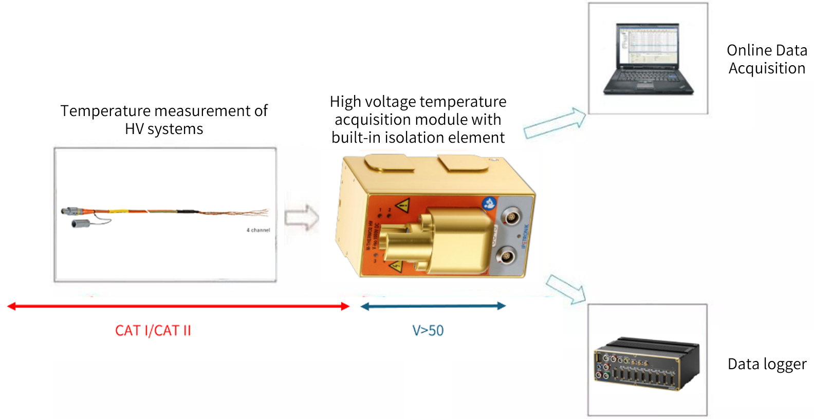
(HV temperature measurement system)
IV. Datalogger Acquisition System
The datalogger acquisition system is shown in the figure below. The datalogger acquisition, which collects data from vehicle ECU and module data, can be used to establish a connection with a computer via USB flash drive/network cable/Wi-Fi/GPRS/4G and upload the data to the analysis software such as IPEmotion, then the data can be displayed and analyzed.
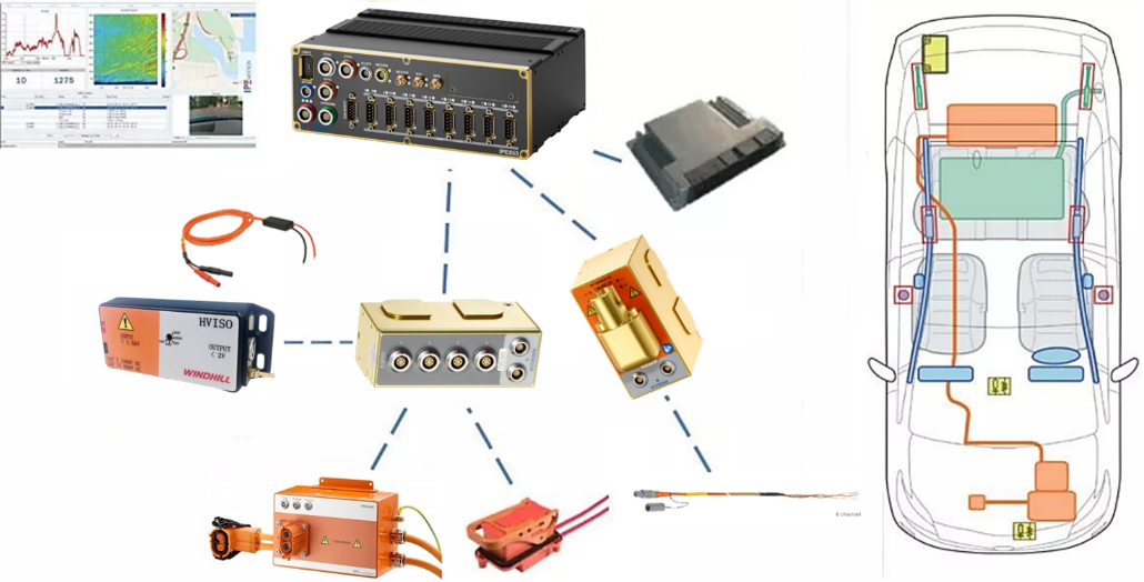
(Data Logger Acquisition System)
Advantages of using a datalogger acquisition system:
• Safety:
There is no need to touch any high voltage cables and no additional installation required.
• Speed:
Simple to install, just connect to the vehicle bus and easily configure using IPEmotion, then power up and the data is stored directly in the logger.
• Flexible configuration:
Not only it can be woken up using the CAN bus, but it can also be set up to trigger storage or multiple storage groups, as well as wireless data transfer.
V. Examples of Actual Measurements of EV
• Voltage Measurement(Battery/PDU/DC)
The following figure shows a physical diagram of the field connections for the entire system. The two positive and negative cables of the current limiter are connected to the measurement point and pass through the isolation module to the voltage acquisition module, which then transmits the data to a computer or datalogger via a data communication cable.
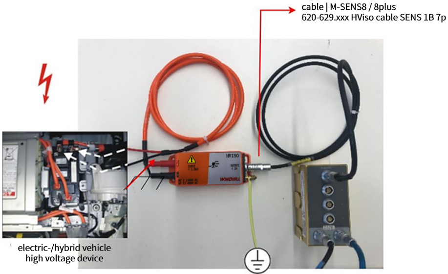
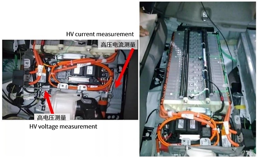
(Example of high voltage measurement)
• Current Measurement
The figure below shows an example of current measurement where a Hall closed loop current sensor and a high voltage shunt are used.

(Example of high-voltage current measurement)
• Temperature Measurement
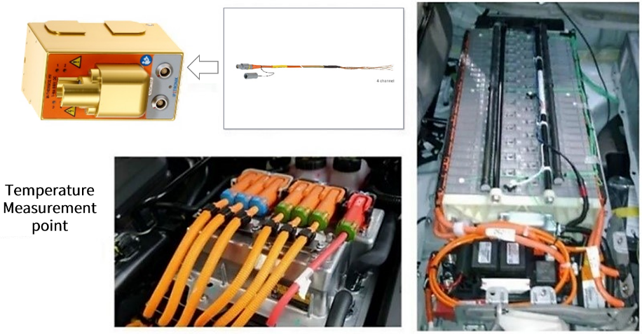
(Example of high-pressure temperature measurement)