New Breakthroughs in Thermal Management for EV: WINDHILL provides multi-faceted testing and optimization solutions
As an important measure to achieve energy savings, enhance the economics, and guarantee the safety of vehicle, thermal management technology plays a crucial role in the Vehicle R&D. The thermal management system of traditional fuel vehicles mainly includes the engine, the transmission cooling system, and the automotive air conditioning, while the thermal management system of electric vehicles adds heat pump thermal management, motor electric control thermal management system and battery thermal management system to the thermal management architecture of traditional ICE vehicles. Almost thermal management includes all parts of the electric vehicle and their complex level will be even higher. That is why thermal management becomes the key development for automakers.
I. Backgrounds
Compared with thermal management in conventional vehicles, the thermal management demands for battery, motor, electronic components, and other components are added for electric vehicle. This means that thermal management strategies for new energy vehicles are more complex and have higher requirements:
• Long test cycles
• Power battery is sensitive to temperature
• Complicated test conditions
• Extreme condition simulation may cause potential safety hazards for test staff, such as high temperatures and high voltage and more
• Multiple data acquisition systems are difficult to synchronously acquiring signals
• Deep mining and analysis of data
WINDHILL specializing in thermal management fields, including automotive air conditioning and electric vehicle battery thermal management systems, and has accumulated years of professional experience. From bench design and development to vehicle road tests, we provide you with a comprehensive testing solution.
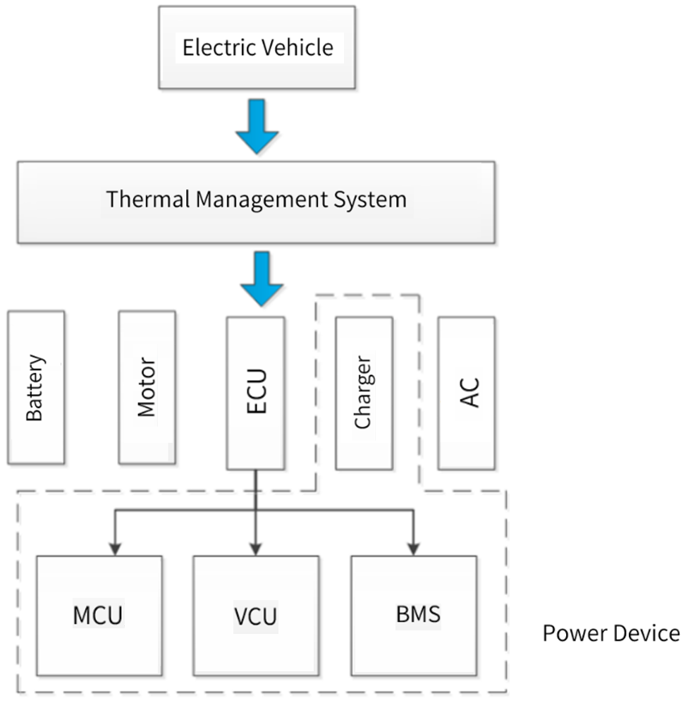
(Fig.1 Block diagram of electrical equipment for new energy thermal management system)
II. Thermal Management Testing
Thermal management system mainly includes: air conditioning refrigeration system, heating system, motor cooling system and battery temperature control system.
The thermal management test mainly tests the management strategy between each loop, including:
1. High& low-temperature loop thermal management strategy:
low-temperature discharge heating control strategy; low-temperature charge heating control strategy; high-temperature discharge cooling control strategy; high-temperature charge cooling control strategy; motor high-temperature cooling control strategy.
2. Air conditioning system and loop cooling coordination strategy.
3. Air conditioning system and loop heating coordination strategy.
III. Solution
| Air conditioning system
The air conditioning system not only affects the driving comfort of passenger vehicles, but also involves safety and energy consumption. Electric vehicles with traditional air conditioning systems usually use PTC for heating the passenger compartment, but this greatly reduces the range of electric vehicles. The EV heat pump air conditioning system is an improvement based on traditional vehicle air conditioning systems, achieving the transfer of heat from low temperature range to high temperature range, featuring high Coefficient of Performance (COP), and can reduce power consumption.
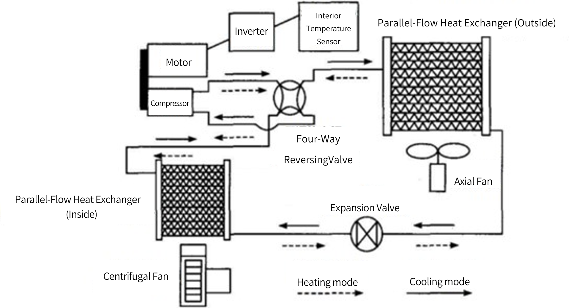
(Fig. 2 Schematic diagram of the operation of new energy air-conditioning system equipment)
When there is a cooling requirement in the passenger compartment, the air conditioner operates according to the traditional air conditioning loop. Air conditioner refrigerant flows through the air conditioner compressor, condenser, expansion valve, and evaporator for refrigeration; When there is a heat requirement in the passenger compartment, the refrigerant loop of the air conditioner flows through the air conditioning compressor for compression, and release heat in the in-vehicle heat exchanger, and then enters the outdoor heat exchanger through the electronic expansion valve for evaporation and heat absorption, thus forming a complete heat pump cycle.
Testing solution:
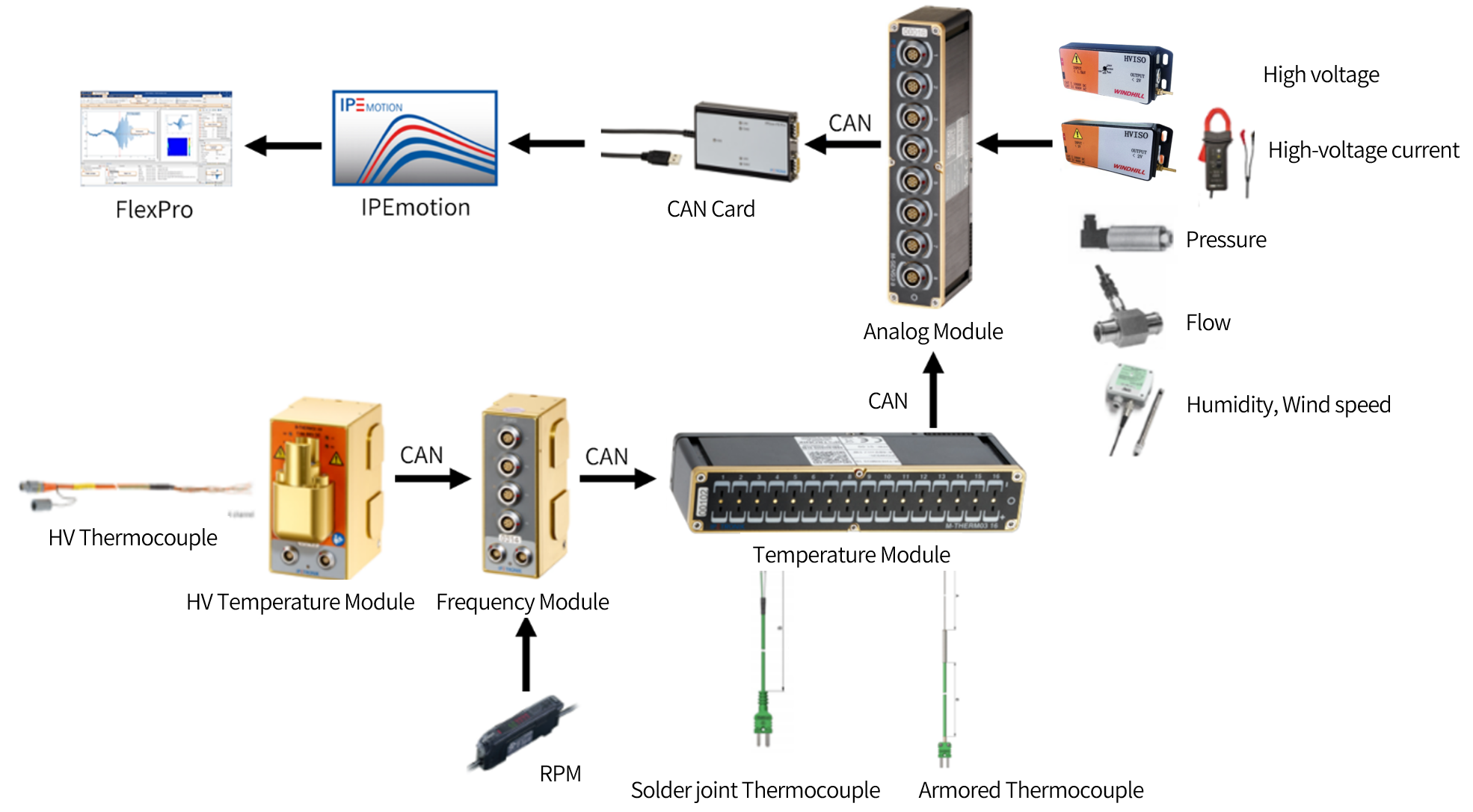
(Fig. 3 Schematic diagram of equipment connection for air-conditioning thermal management test system)
| Motor cooling system
The motor cooling system is similar to the engine cooling system and generally consists of components such as an electric pump, radiator, cooling fan, expansion tank, and pipelines . If the cooling method of electronic power components (motor controllers, DCDC) in the vehicle is the same as that of the motor, the power components are usually also connected in series in this loop, and arranged according to the temperature characteristics of each component.
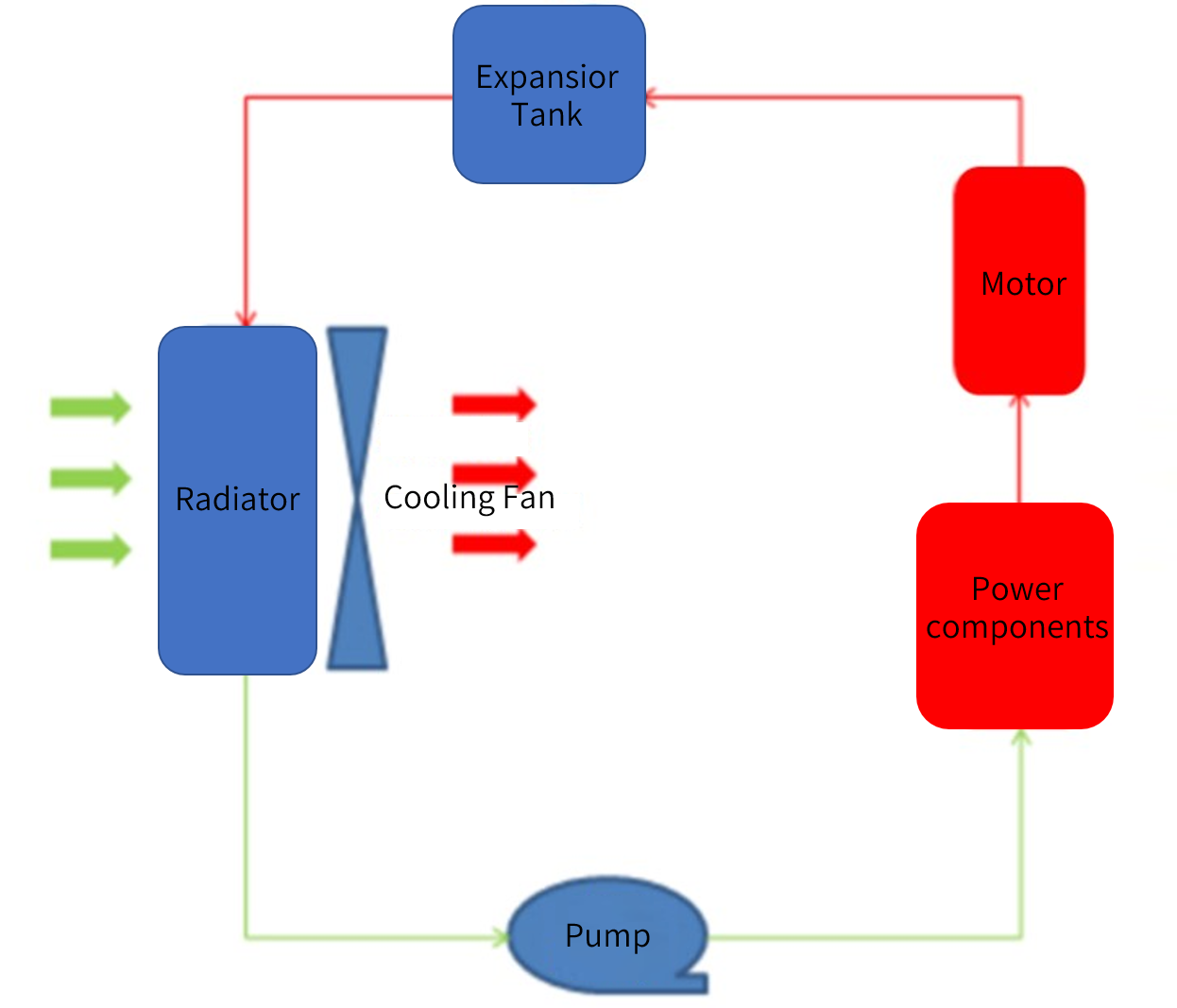
(Fig. 4 Schematic diagram of motor cooling equipment)
| Testing solution:
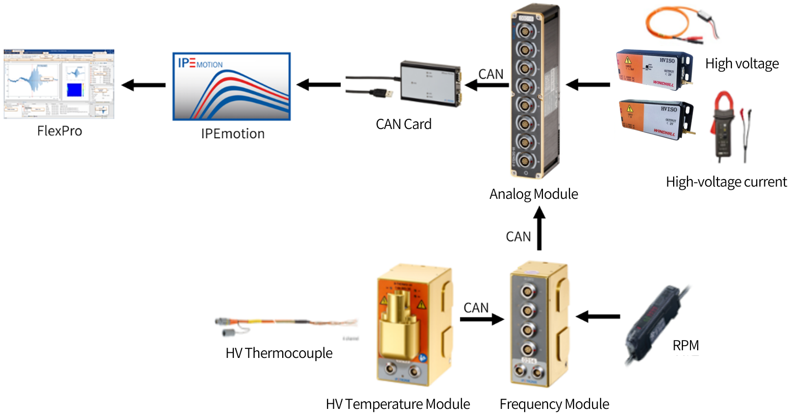
(Fig. 5 Schematic diagram of motor cooling system test equipment connection)
| Battery temperature control system
The cooling modes of power batteries are mainly divided into air cooling, liquid cooling, and direct cooling. The air cooling mode uses natural wind or the cooling air in the passenger compartment to flow across the surface of the battery for heat exchange and cooling. Liquid cooling generally uses separated coolant pipelines to heat or cool the power battery, and this method is currently the mainstream method for heating and cooling. The direct cooling system eliminates the cooling pipelines of the power battery, and directly uses refrigerant to cool the power battery.
Water cooling mode, that is, the battery adopts water cooling to exchange heat. Usually a heat exchanger is added to couple the cooling cycle, and the heat of the battery is taken away through the refrigerant. The whole system mainly includes: electronic pump, heat exchanger, battery heat sink, PTC heater and expansion tank. Its structure is shown in the following figure.
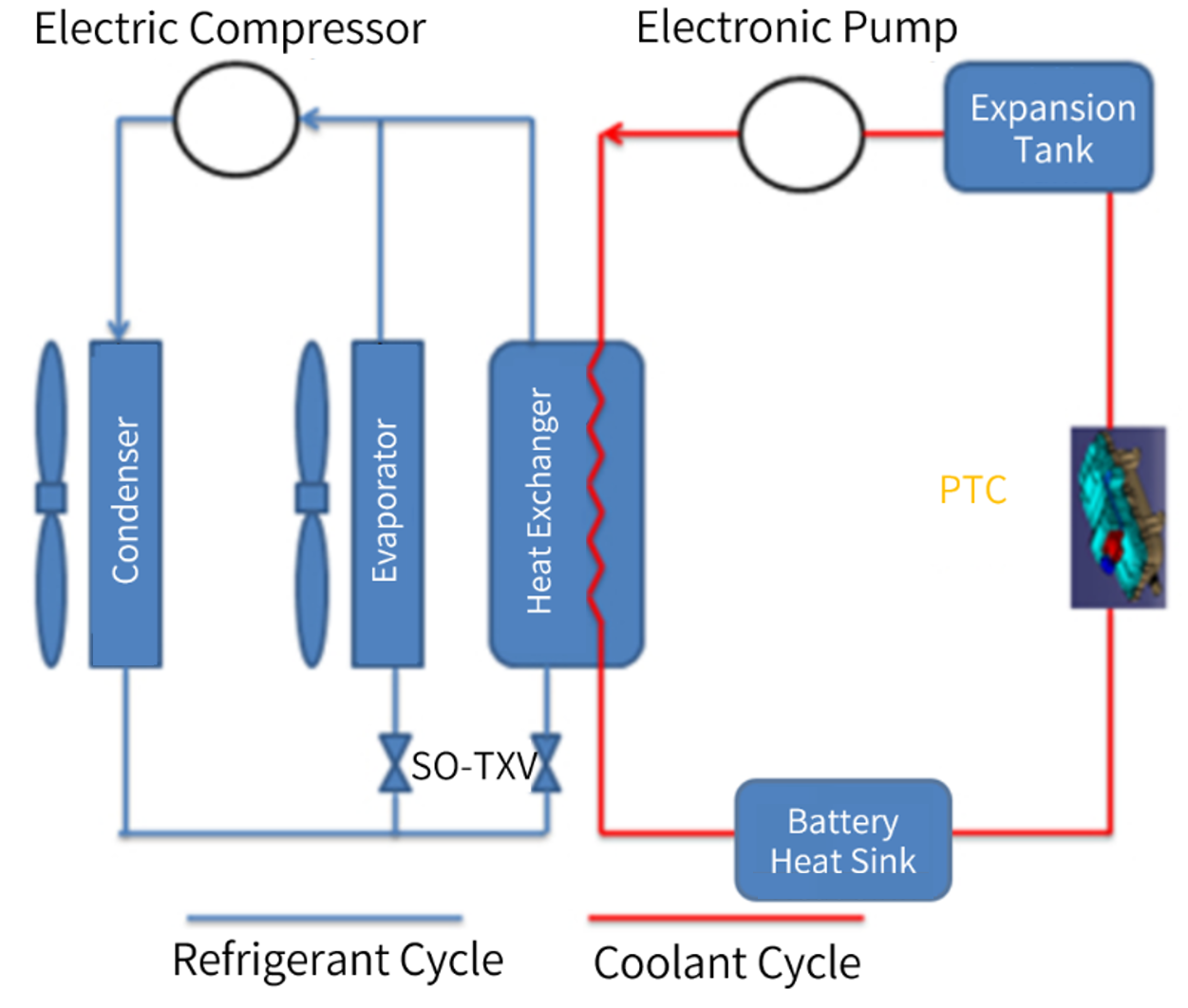
(Fig. 6 Schematic diagram of battery cooling system equipment)
Test solution:
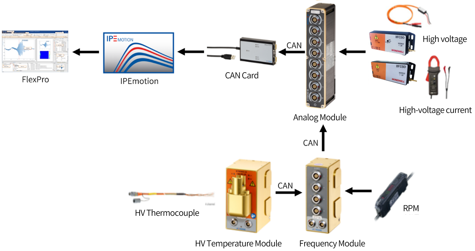
(Fig. 7 Schematic diagram of battery cooling system test equipment connections)
IV. Solution Advantages
1. Support EV high voltage testing, with protection level IP67/IP54.
2. Based on a CAN network, a CAN bus leads off, which can be directly connected to collect data.
3. The flexible and convenient combination not only reduces development time and costs, but also increases device efficiency.
4.Conduct Sensor point distribution test in accordance with national standards and actual user requirements.
5. The mainstream road test device can be used under extreme harsh environments. The operating temperature of the M model: -40~125°C.
6. All channels synchronously acquire data.
7. The module has high measurement accuracy, ±0.013% for K-type thermocouple, ±0.031% for T-type thermocouple, ±0.05% for voltage, ±0.05% for current, and ±0.01% for frequency.
8. Anti-shock and vibration resistant, testing during the development and production stages.
9. All measurement channels, buses and power supplies are fully isolated.
10. Sensor break detection, power supply short circuit protection.
11. On-board power supply: 9~36VDC.
12. Modular design, distributed or centralized installation, and scalable.
13. Support multiple type of buses(CAN/CAN FD, LIN, FlexRay and Ethernet) and protocols(OBD, UDS, DoIP, DBC and XCP/CCP).
V. Products
| Hardware
1. Analog module
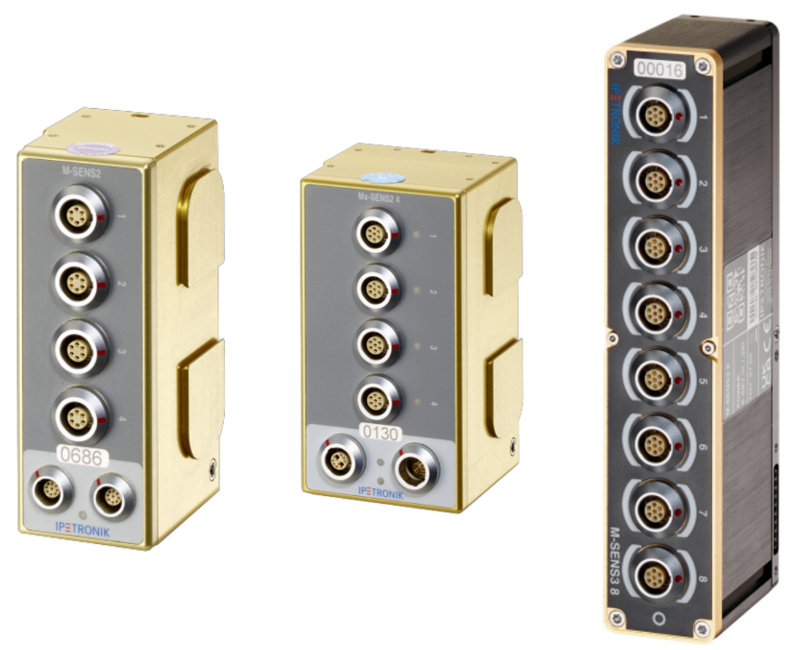
(Fig. 8 Analog Data Acquisition Module)
• 4/8 channel optional
• The number of test channels can be flexibly combined according to demand
• Applicable to analog data testing
• High-voltage analog testing supported with isolation device
• Measurement range: ±10mV~±100V, ±20mA
• Each channel supplies ±2.5V~15V power to the sensor separately
• Complete optoelectronic isolation between channels
• The operating voltage is fully applicable to vehicle power supply
• Protection level IP67
2. Temperature measurement module
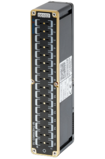
(Fig. 9 Temperature Data Acquisition Module)
• 16-channels K, T-type thermocouple measurement module, 16 Channel General Purpose Thermocouple Module
• Single channel sampling frequency: up to 200Hz
• Operating temperature: -40~125℃
• Measurement range: Type K(NiCr/NiAl)-270...1372°C、Type T(Cu/CuNi)-270...400°C;
• On-board power supply: 6~59VDC
• Miniature thermocouple plug(DIN IEC 584)
• Module protection level IP67
3. High voltage temperature measurement module
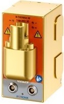
(Fig. 10 HV Temperature Measurement Module)
• Each channel has an independent high-voltage safety connector
• Cold junction compensation for each channel
• Status indicators for each measurement channel
• On-board power supply: 9~36VDC
• Measurement data output as CAN signals
• Electrical isolation, bipolar up to ±846VDC
• Designed for engine compartment applications
• Rugged and compact module for harsh environments
4. Frequency measurement module
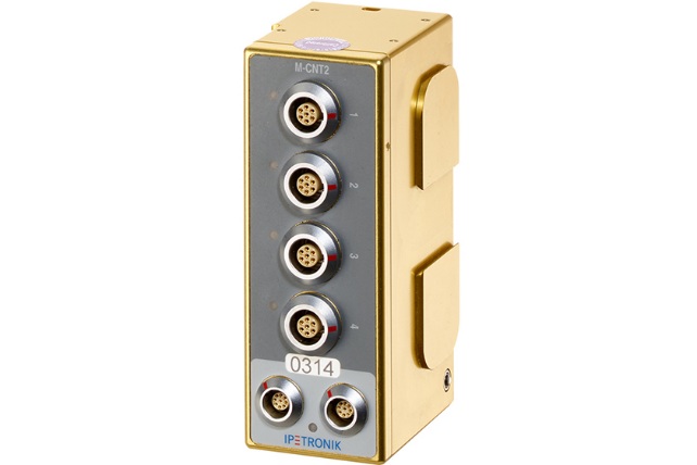
(Fig. 11 Frequency Measurement Module)
• 4-channel pulse frequency measurement module
• Signal mode: 0.03~200kHz(frequency), 0.01%~99.99%(duty cycle), 1us/200s(pulse width)
• Event counter: reset function mode(no reset, time, overflow)
• Rotation direction detection(frequency, event counter)
• Single channel sampling frequency: up to 5kHz
• Accuracy(25℃ ambient temperature): ±0. 01%
• adjustable on/off threshold
• Onboard power supply: 9~36VDC
• Operating temperature: -40~125℃
• Independent power supply for each input sensor: 0~15V
• 4 channel LED light measurement status indication
• Shielding between channels without mutual interference
| Software
1. Measurement software IPEmotion — configuration, acquisition, storage
Advantages:
• The data measured by the data acquisition module is accurate and reliable
• Ensure the reasonable cooling efficiency of the refrigeration system
• The Climate plugin provides Log-ph diagrams for intuitive analysis of the entire process of a refrigeration system
• The prerequisites for using Climate are IPEmotion Professional Edition, the Climate installation package, and installation of REFPROP(NIST)
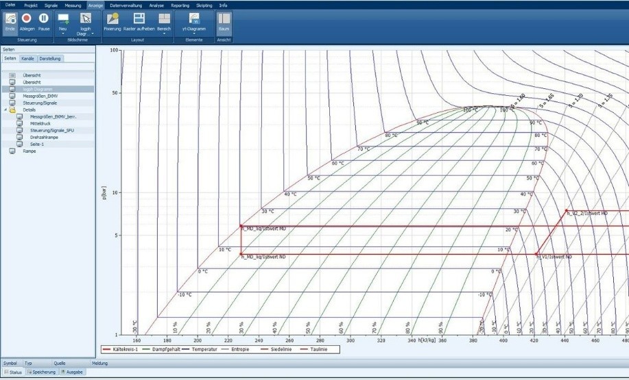
(Fig. 12 IPEmotion Climate Package Functionality Interface)
2. Analysis software FlexPro — Display, Analysis, Reporting
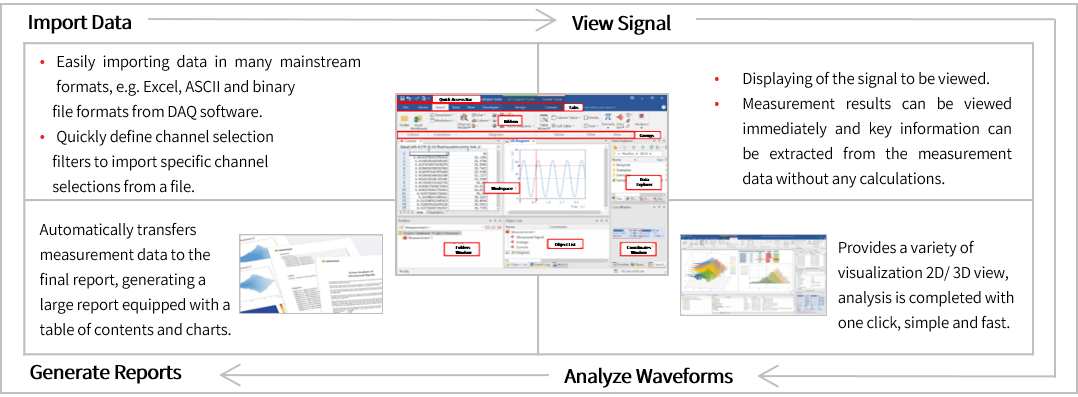
(Fig. 13 Introduction to FlexPro Software Functions)