In-Depth Analysis: ODX Diagnostic Database as ISO22901-1 Standard

I. Background and Challenges
Against the backdrop of the increasing development of the global automotive industry, the requirements for vehicle diagnostics technology in the industry are also rising. Currently, the ODX diagnostic database has been widely used by major OEMs and plays a crucial role in the entire life cycle of ECUs. It not only standardizes the diagnostic process, but also ensures the consistency and reliability of data exchanges between different models and different segments, thus ODX becoming an important factor in promoting the progress of vehicle diagnostics technology.
However, there is a certain technical threshold to build an ODX database, and the large amount of data input work at the vehicle level is also very challenging, while using traditional manual editing tools is not only time-consuming and laborious, but also prone to errors and omissions. For engineers, this is undoubtedly a daunting task.
II. Introduction to ODX
| Overview:
ODX (Open Diagnostic Data Exchange) is a standard diagnostic data structure developed by ASAM, which has been under development since 2002 and was officially released in 2008 as the ISO 22901-1 (ODX) standard. The core purpose of the ODX standard is to ensure that ECU diagnostics and programming information can be transferred in a consistent data format between system suppliers, vehicle manufacturers, service dealers, and various diagnostic tools.
The ISO 22901-1 standard describes the definition of a data model for ECU diagnostics and programming data,contains data models describing all diagnostic data of the vehicle and the ECU, such as DTC, data parameters, input/output parameters, ECU configuration (variant coding) data, and communication parameters, as well as descriptions of the relevant vehicle interfaces in the Unified Modeling Language (UML), and also includes the data exchange format, i.e. the implementation of the Extended Markup Language (XML) schema structure.
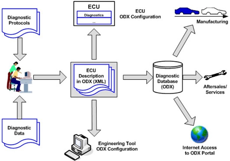
(Figure 1 Usage of ODX data in the ECU life cycle, from: ISO22901-1 P3)
Diagnostic data in ODX format will allow MVCI (Modular Vehicle Communication Interface) devices to communicate with the ECU and interpret the diagnostic data contained in the messages exchanged between the external test equipment and the ECU. For external testing equipment that meets ODX standards, no additional software programming is required to convert the diagnostic data into technician-readable data.
| File structure:
The ODX file contains the following layers, using version 2.2.0 as an example:
*.odx-c Communication Parameter Specification
*.odx-cs Communication Parameter Subset
*.odx-d Diagnostic Layer Containers
*.odx-e ECU Configuration
*.odx-fd Function Dictionary
*.odx-v VehicleInfo Specs
*.odx-f Flashs
*.odx-m Multiple ECU Job Specification
| The following figure shows a simple example of *.odx-d:
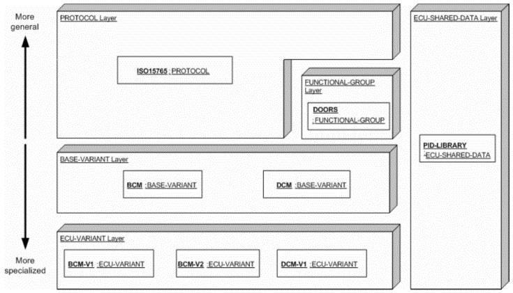
(Figure 2 Diagnostic layers overview example,from: ISO22901-1 P31)
■ Communication Parameter Specification "-C Layer"
A communication parameter specification contains one or more protocol stacks (ProtStacks) that reference a set of communication parameters defined in a subset of communication parameters (COMPRAM-SUBSET).
■ Communication Parameter Subset "-CS Layer"
• Communication parameters and their values are defined in the Communication Parameters subset, e.g., network layer timing parameters, application layer timing parameters, baud rate, etc.
• Each subset may define communication parameters for different layers (e.g., application layer, transport layer, physical layer).
■ Diagnostic Layer Containers "-D Layer"
• Describe the communication process between the Tester and ECU, including the request, response format of communication service and the types of parameters used.
• A Diagnostic Layer container may contain one or more diagnostic layers (DIAG-LAYER).
• Each diagnostic layer (DIAG-LAYER) consists of five subgroups representing a hierarchical arrangement of the ASAM database model:
Shared Data (*. -SD): Contains generic diagnostic objects, such as units, that are often reused by other layers;
Protocols (*. -PR) : Describes generic protocols (request/response), e.g. containing ISO14229-1 (UDS standard);
Functional Groups (*. -FG) : Describes ECU services with the same similar function, accessing the ECUs simultaneously via functional addressing;
ECU Base Variants (*. -BV) : Contains the services of an ECU platform, usually with 'Hardware part numbers' etc;
ECU Variants (*. -EV) : Contains variables derived from the base variables, usually corresponding to specific suppliers.
ECU Configuration "-E layer": Contains ECU configuration information, including enabling/disabling optional functions according to the specific vehicle environment, location, etc. It is mainly applied to ECU production and after-sales stage.
Function Dictionary "-FD layer": Describes function-specific diagnostic information.
VehicleInfo Specs "-V Layer": Defines the vehicle topology, channels.
Flashs "-F layer": Description of the data required for flashing, such as the memory layout, the logical structure of the flash segments, and information that must be used for diagnostic services or work on the flash data.
Multiple ECU Job Specification "-M Layer": Definition of a multiple ECU diagnostic Job with access to multiple logical links.
III. Solution
Based on years of experience in diagnostic development, WINDHILL has independently developed VisualODX diagnostic design tool, which supports one-click conversion of Excel diagnostic questionnaire to ODX/PDX/CDD/DEXT/ATXML files, with powerful functions, which can greatly reduce the manpower cost and easy to operate, thus accelerating the development progress.
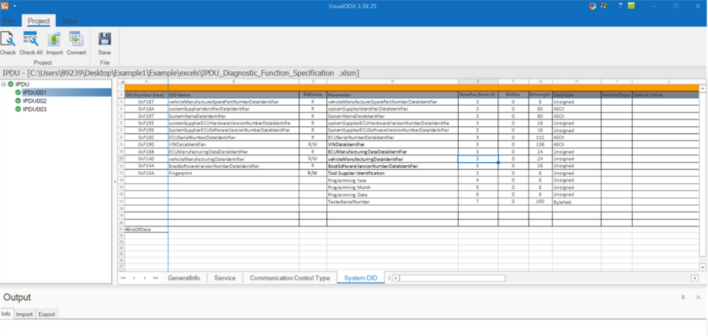
(Figure 3 VisualODX software interface)
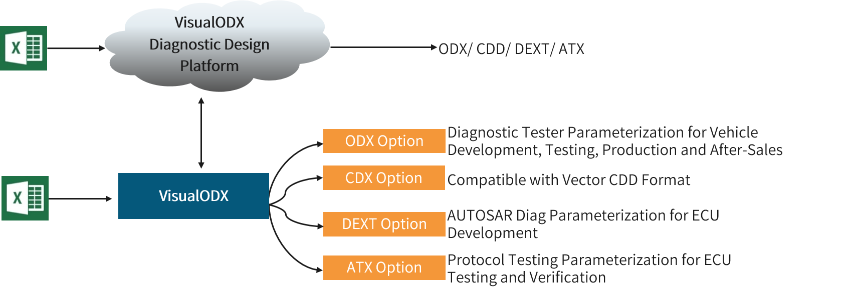
(Figure 4 VisualODX product family)
| Functions:
1. Template:Import standard ODX template files to complete the ODX architecture building.
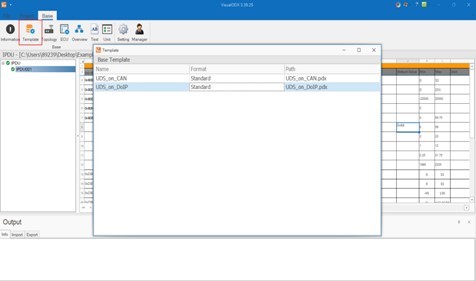
(Figure 5 Base-Template template import)
2. Link File:Import diagnostic questionnaire (Excel), generate *.odx-d, *.odx-e, *.odx-f files to build a complete diagnostic database; multiple EVs can be added to ECU and the number is unlimited.
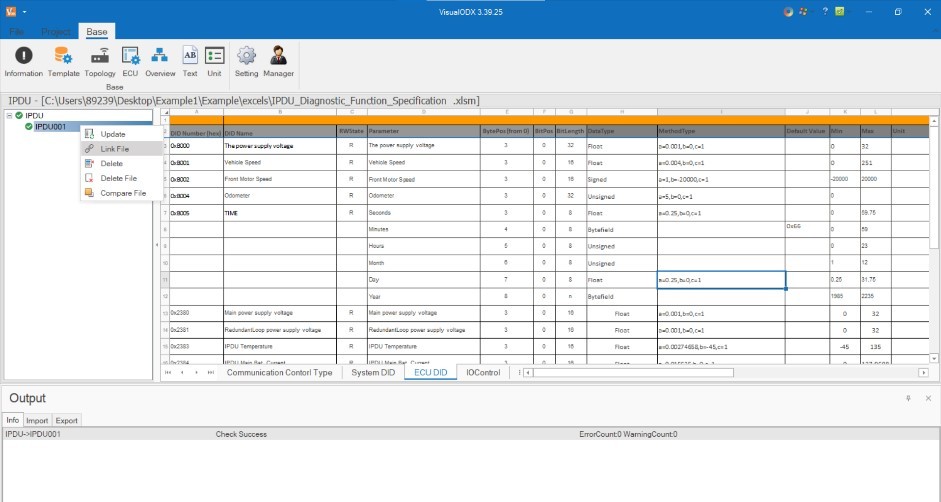
(Figure 6 Project-Link File Import Excel)
3. Check:Configuration file integrity check, errors can be located with one-click.
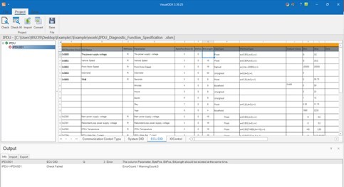
(Figure 7 Project-Check)
4. Convert:Supports converting ODX/PDX/CDD/DEXT/ATXML files.
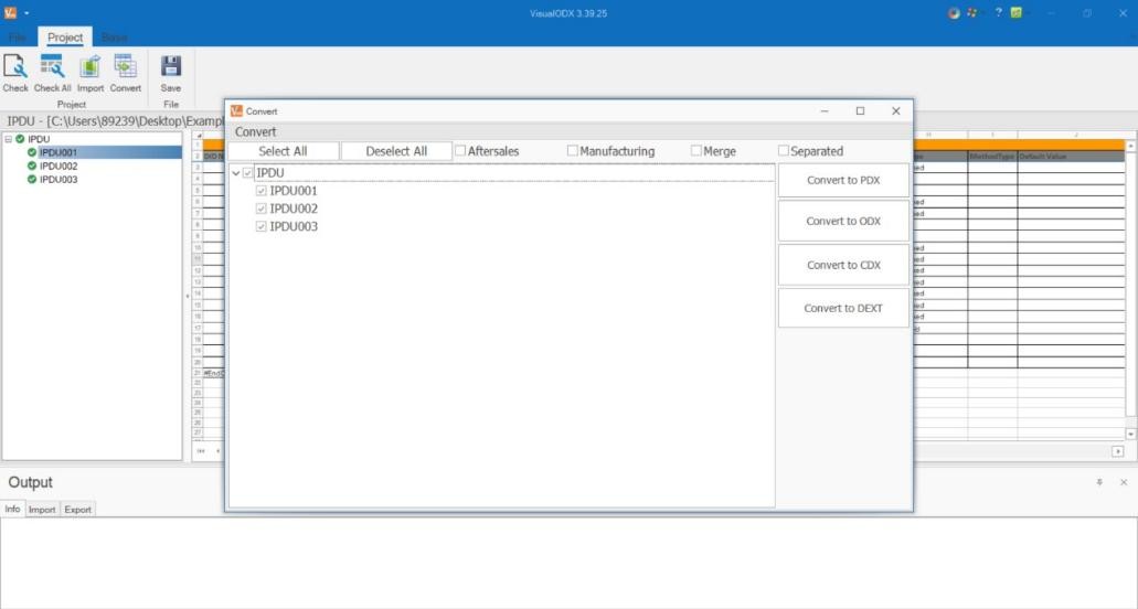
(Figure 8 Project-Convert)
| Advantages:
• ODX templates and Excel templates that follow ASAM standards are combined with double checking to effectively ensure the completeness and accuracy of the generated data;
• The standard Excel template, convenient for users to quickly realize the whole vehicle Excel questionnaire creation;
• Innovative project configuration interface for easy project engineering management;
• One-click conversion button to automatically generate ODX/PDX/CDD/DEXT/ATXML files;
• Supports importing Excel sheets of single or multiple ECUs with unlimited number of Excel sheets;
• Supports exporting ODX/PDX/CDD/DEXT/ATXML files for a single ECU or all ECUs;
• High conversion efficiency to meet the conversion needs of large amounts of data;
• Support for user-customized Excel diagnostic questionnaires.
IV. Summary
The important role of diagnostic database in the whole vehicle life cycle cannot be ignored. By using VisualODX diagnostic design tool, not only can we greatly save the time of building the database, but also can effectively improve the work efficiency, and ensure the high quality management and maintenance of the database in all stages of the ECU chain.