Real-time Energy Consumption monitoring solution for EV Charging Piles
I. Background
With the rapid development of new energy vehicles, electric vehicles brands like Tesla, BYD, NIO, XPENG and Li Auto are becoming more and more popular in our daily life, which shows that electric vehicles are gradually being recognized by the public nowadays. Compared with gasoline cars, electric cars need to be charged, so the disadvantages of electric cars (short driving range, long charging time, etc.) are becoming more and more obvious. Only by optimizing the performance of charging piles, shortening the charging time, improving the using experience of charging piles, and enhancing their convenience can we lay a solid foundation for the popularization of electric vehicles.
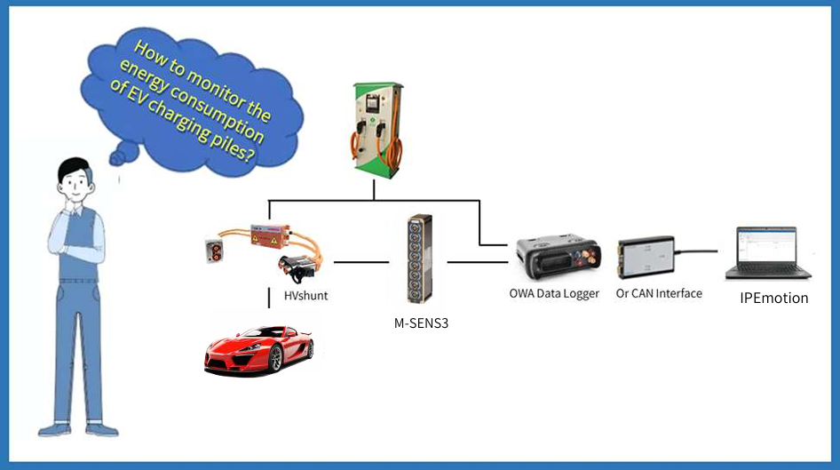
However, at present, the power supply company has no effective monitoring means for the real-time energy consumption of electric vehicle charging stations and parking lot charging pile equipment, which can only monitor the power information of master meter, but not the power consumption of the equipment behind the master meter. In this case, a device that can detect and record the energy consumption of charging piles during the charging process of EV.
II. Solution
Hardware Support
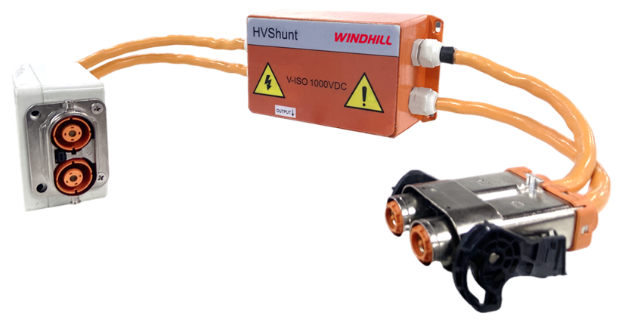
■ HVshunt
Main features:
• Available for electric and hybrid vehicles;
• Can be tested without breaking the wire;
• High voltage input up to 1500VDC;
• Customer-specific plugs for connection to high-voltage networks;
• Built-in high voltage conversion module;
• Can be directly connected to the analog module, M-SENS3.
Main parameters
• Working voltage: 9~36V;
• Conforms to CAT Ⅰ standard application: ±1000VDC;
• Conforms to CAT Ⅱ standard application: 600VAC@50…60Hz;
• High voltage measurement range: ±1500VDC;
• Current measurement range: ±1000A (customizable selection range).
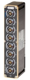
■ IPETRONIK M-SENS3 8
Main features:
• Measurement modes: voltage, current and frequency can be freely selected for each channel input;
• 8-channel sensor excitation (single bipolar 15V);
• Measurement data is output to CAN FD;
• Galvanic isolation (input, CAN, power supply, housings);
• Designed for engine compartment applications;
• Ruggedized compact modules for harsh environments.
Main parameters:
• Working voltage: 6~59V;
• Power consumption: 2.7W;
• Channel sampling rate: 2/5/10min,1/2/5/10/100/200/500/1000/5000Hz;
• Sensor voltage measurement range: ±0.01/0.02/0.05/0.1/0.2/0.5/1/2/5/10/25/100V;
• Sensor current measurement range: 0~20mA, ±20mA;
• Frequency measurement range: 0~200Hz.
Device Connection
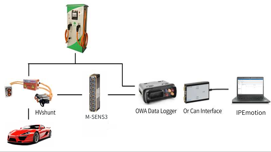
(System connection diagram)
Advantages
In order to ensure the reliability of the charging process, the Charging CAN must be an independent dedicated communication line. The bus system utilizes the CAN2.0B 29-bit extended identifier, with bit allocation in accordance with SAE J1939-21:2006. The physical layer conforms to ISO 11898-1:2003 and SAE J1939-11:2006. Our devices support those protocols and fulfill the above requirements.
When charging an electric vehicle, the charging pile and the vehicle will keep exchanging data, and after connecting our HVshuntin series, not only does it not affect the normal charging and communication of the car, but also collects CAN signals and realizes real-time storing and analyzing of the telegrams.
HVshunt has a built-in high voltage isolation module, which can measure high voltage and high voltage current. The whole equipment leads to two CAN channels, one channel transmits CAN signals such as voltage and current collected by the SENS module, and the other channel transmits CAN signals from the charging pile.
Software Support
The IPEmotion software allows you to view the measured voltage and current values online in real time, and you can add formulas to the software to obtain power and energy consumption information.

(High voltage ¤t channels)
The software can also view the original CAN messages online in real time and can parse the messages according to the GB/T 27930-2023 standard.
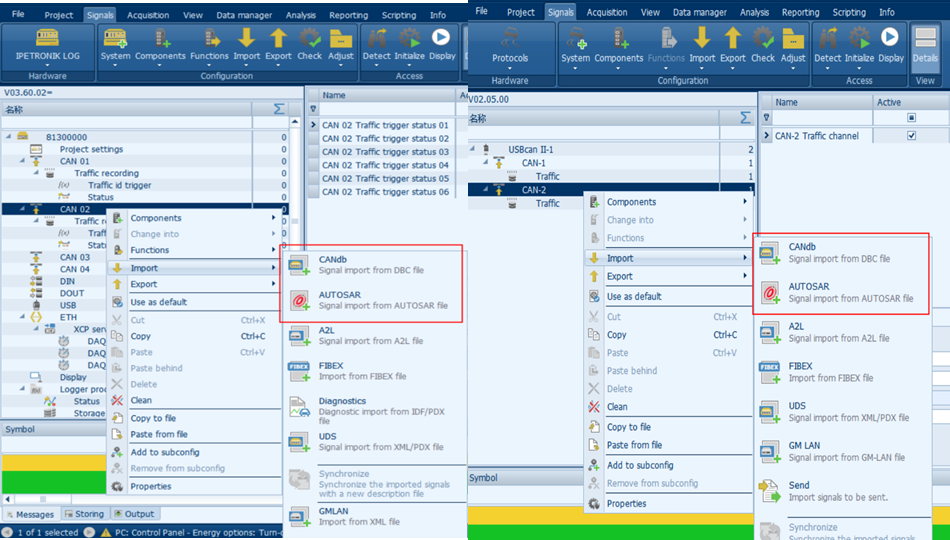
(Import parse file)
During the charging phase, the BMS sends the Battery Charging System (BCS) and Battery Charging Link (BCL) messages to the charger. The charger receives these two telegrams within a specified time and sends the Charger Charging Status (CCS) telegram to the BMS. (It also waits to see if it receives the Charge Stop Telegram BST from the BMS, and if it receives the (BST) then the charger immediately stops charging and sends the Charger Stop Telegram (CST) Message to the BMS in response.)
After receiving the Charge Charging Status CCS message from the charger, the BMS sends the Battery Status Message (BSM) to the charger and waits for the charge to be fully charged. (At the same time, it waits to see if it receives the CST from the charger, and if it receives the CST then the BMS immediately sends the BST to the charger in order to abort the charging.)
When charging at charging piles and electric vehicles, we usually need to pay attention to the following message information in real time:
• Battery Charging System (BCS) message: voltage measurement during charging (V), charging current measurement (A), peak voltage of single power battery and group number, current charge state SOC (%), estimated remaining charging time (min);
• Charger Charging Status (CCS) message: voltage output value (V), current output value (A), accumulated charging time (min);
• Battery Status Message (BSM): power battery temperature upper limit/lower limit, single power battery voltage status, whole vehicle power battery charge status SOC, power battery charging overcurrent, power battery temperature, power battery insulation status and power battery pack output connector status.