IPEmotion Easily Solves Emergency Stop Device Control and Data Storage Problems

1 Background
As we all know, emergency stop plays a very important role in various industrial fields. In an emergency situation, emergency stop can save valuable time, avoid personal injury or equipment damage, and reduce the safety risk, especially in new energy vehicle testing, the emergency stop function is more important for the safety of high-voltage electrical performance considerations.
Getting the emergency stop to work at the right moment is the focus of most tests, and is an important factor in the safety of the entire test. If the equipment can automatically determine the emergency stop conditions and send signals to the emergency stop equipment in time to control the operation of the emergency stop equipment, then this will help engineers to carry out long-term and reliable endurance testing.
2 Solutions
The problem of automatic emergency stops for test equipment can be easily solved by using IPEmotion software, which supports data triggering, automatically controlling the hardware equipment to send a specific signal to the outside world when a certain condition is reached, and the type of signal can be selected according to the type of signal the emergency stop equipment can receive. By combining the IPEmotion software with the measurement modules, the emergency stop signal output of the hardware device can be realized. Depending on the type of signal received by the emergency stop device, the corresponding output signal module can be selected, such as voltage signals, current signals, discrete digital signals and so on.
The following is an example of a voltage output type module. With the IPEmotion software, the hardware device can be controlled to send a 5V voltage signal to the emergency stop device when a certain condition is triggered.
1. IPEmotion software with IPETRONIK data acquisition module can realize the overall equipment temperature, voltage, current, frequency and other signals monitoring.
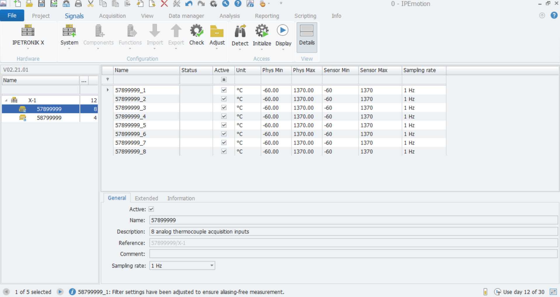
(Figure 1 Configuring the IPETRONIK Data Acquisition Module in IPEmotion Software)
2. Write formulas in the acquisition interface to set the trigger conditions for the emergency stop signal. When the actual value reaches the set warning value, IPEmotion software will control the hardware device to send out 5V voltage value. The emergency stop device will react and cut off the main power supply after receiving the corresponding voltage signal, so that the whole test equipment is powered off, thus safeguarding the safety of personnel and equipment.
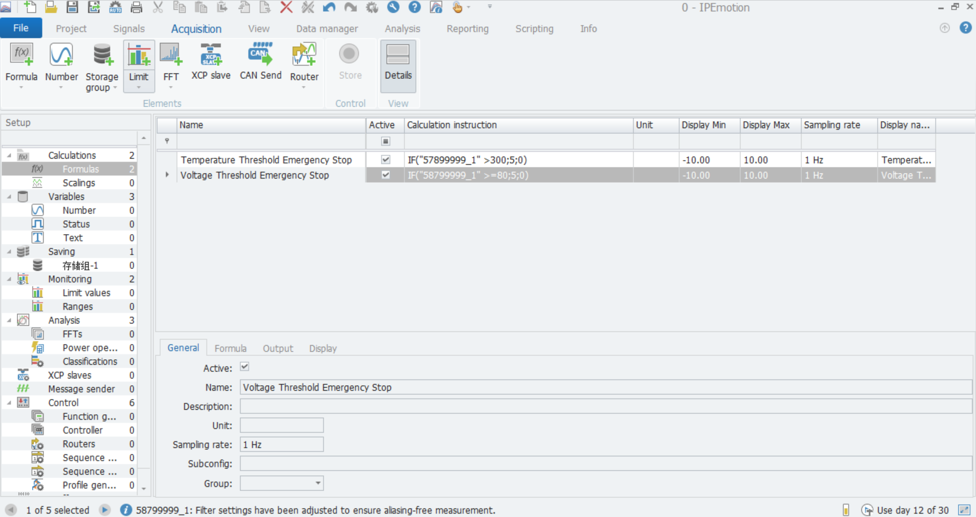
(Figure 2 Setting Up Formulas to Control Data Triggering in the Acquisition Interface)
3. For the moment of equipment failure and before and after the failure of the data preservation problems, through the IPEmotion software can be easily solved, not only the data can be completely retained, but also conducive to the later failure analysis.
IPEmotion has a powerful data storage function, not only can you set up multiple storage groups for simultaneous storage, but also can set up the data recording path, file name and format individually, etc. It also supports a variety of data formats for storage, and you can choose to set them up according to your needs.
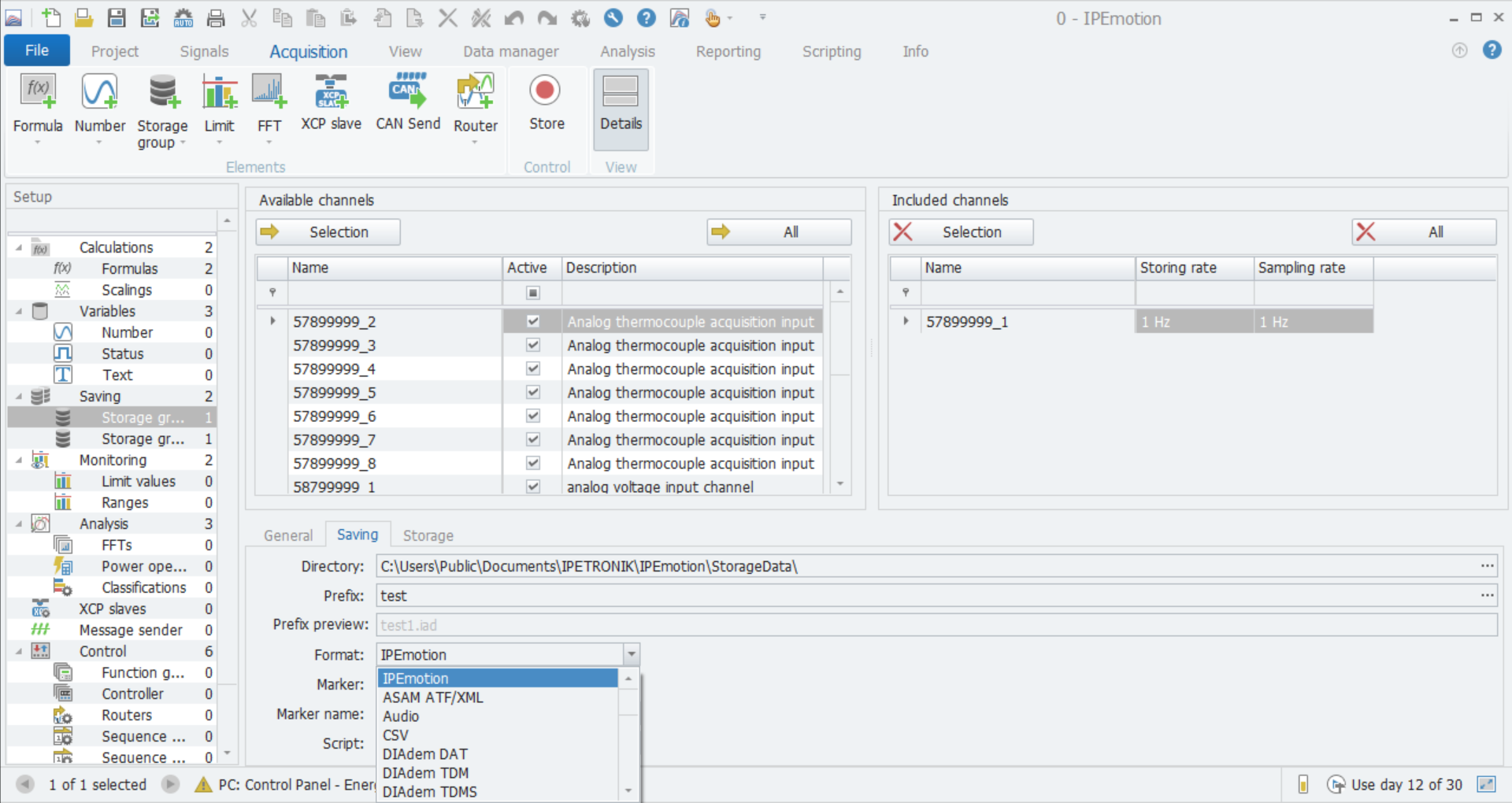
(Figure 3 IPEmotion Storage Configuration Interface)
The IPEmotion software can be set to record data at the time of a fault and for a number of hours prior to the fault by setting a trigger data storage mode, which can also be set to suit your needs. However, if the preset trigger value is not reached, IPEmotion will not store the data, thus reducing data redundancy.
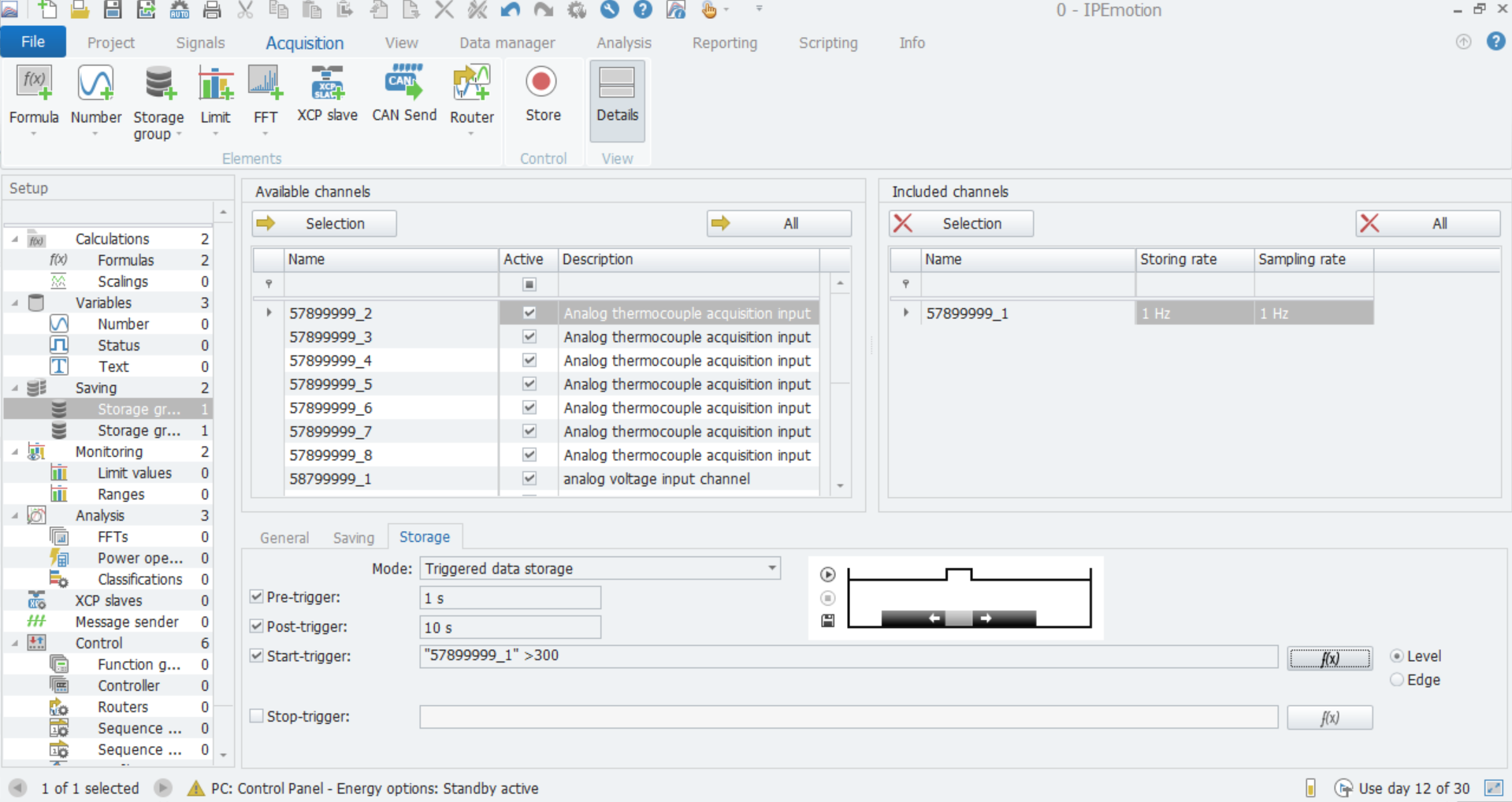
(Figure 4 IPEmotion Storage Mode Settings)
3 Hardware
Hardware Devices - Temperature Measurement Modules and Analog Input Modules
Temperature Measurement Modules:
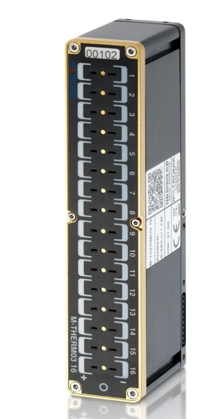
(Figure 5 Temperature Measurement Module M-THERMO3 16)
• 16-channel composite thermocouple module supporting K/T/N/S/R/E/J/B/C thermocouple types;
• Single channel sampling frequency: up to 200Hz;
• Operating temperature: -40~125℃;
• Measuring range: Type K-270~1372°C, Type T-270~400°C;
• Vehicle power supply: 6~59VDC;
• Miniature thermocouple plug (DIN IEC 584);
• Module protection level: IP67.
Analog Input Module:
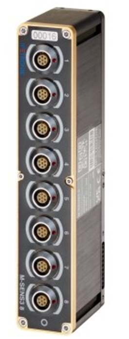
(Figure 6 Analog Measurement Module M-SENS3 8)
• 8 analog measurement channels;
• Each input channel is free to choose the working mode: voltage, current, frequency;
• Measuring range: ±10mV~±100V, ±20mA, 0~200Hz;
• Measurement accuracy: in the ambient temperature of 23 ℃, ±0.05% (± 0.01~±0.02V), ±0.025% (±0.05~2V), ±0.05% (5~100V), ±0.05% (current);
• Single channel sampling rate: up to 5kHz;
• Supports CAN/ CANFD output;
• Individual power supply to the sensor from each channel: ±2.5~15V;
• Complete electrical isolation between channels;
• Magnetic connection between modules, no connecting wire required for inter-module connection;
• Operating voltage: 6~59V, fully applicable to vehicle power supply;
• Operating temperature: -40~125℃;
• Protection level: IP67.
4 Software
Measurement Software IPEmotion - Configuration, Acquisition, Storage and Analysis
IPEmotion Advantages:
• Configuring data acquisition equipment and setting up formula algorithms;
• Providing a variety of visual components to display data online;
• Analyzing the stored data after the test is completed;
• Finally, generating report.
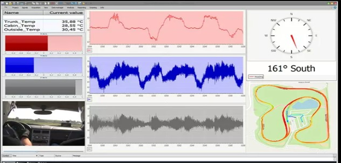
(Figure 7 IPEmotion Software Data Display Screen)
Previous Updates
▶ Real-time Energy Consumption monitoring solution for EV Charging Piles